Laser from the CD drive. How to remove a laser from a DVD drive. Connecting a laser diode: diagram, operating features
I bring to your attention an article describing the creation of a powerful red laser capable of lighting matches and burning through various objects!
To obtain a burning red beam (650nm) you need writing DVD drive, maybe old and broken (most likely the laser diode is working there). A CD-RW drive is also suitable, as well as writing Blu-ray drive, only the first one will shine almost invisible infrared ray(780nm), and the second is violet (405nm).
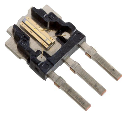
We disassemble the drive and look for something like this laser diode:
It is inserted into a metal heat-sinking housing. And this body is also inserted into a metal base. It is up to you to decide whether to remove the LD from the base and body or not. It’s definitely not worth pulling out flat, frameless ice cubes. I left it in the case - the radiator, and pulled it out of the base. This all affects heat removal, which necessary! I have come across the opinion that the heat sink of the carriage is not enough when powered by non-pulse current. This may be true for some drive models, or if maximum power is required.
DVD-RW has 2 laser diodes, one infrared for playing and recording CDs, and the second red for recording and playing DVDs. You can make 2 lasers! And from BD-RE - three! IN modern models DVD-RW uses dual LDs on one chip.
It is impossible to turn on red and infrared diodes simultaneously at high current in such assemblies! The laser diode is afraid of static electricity, so as soon as you see 3 legs LD, wrap their bare wire!
Do not direct the laser beam into the eyes or at reflective surfaces, as this may lead to partial or complete loss view!!! This also applies to the invisible infrared laser because it has the same burning power as red or violet!!!
The laser diode must be powered with a certain current, exceeding which causes the LED to overheat, as a result it will shine like a regular LED or even burn out. To avoid this, you need to assemble a special circuit - a driver.
Scheme 1:

Capacitors any voltage(from 3V) C1 capacity 0.1uF And C2 capacity 100uF protect against static electricity and ensure smooth transient processes. After connecting them to the LD, the wire can be removed from the terminals. A minus signal is applied to one of the terminals and to the housing., to the second pin plus, the third pin is not used. The location of the poles is clearly visible in the second diagram. For some LDs, + is supplied to the body. I've seen this with 808nm LEDs. Dual diodes have a common minus G in the middle terminal, plus the outer terminals: C for powering the CD, D for powering the DVD.
To power this circuit, it is convenient to use a cell phone battery or 3 AA batteries. Battery voltage may be higher than specified, especially immediately after charging (up to 4.2 V, with the indicated 3.7 V), so check it with a multimeter!
Approximate correspondence between DVD recording speed, current strength and power of laser diodes:
16x - 250-260mA. Power 200mW.
18x - 300-350mA.
20x - 400-450mA. Power 270mW.
22x - 450-500mA. Power 300mW.
24x - 450-500mA.
IR LD power in CD-RW is 100-200 mW.
The power of violet LD in BLU-RAY RW is 60-150 mW.
The power of the violet LD in non-writing BLU-RAY is 15 mW.
The above relationships between recording speed and current can be not applicable to all accounts, for example, when checking 2 dual LEDs on one crystal, it turned out that at a voltage of 3V, one of them received a current of 260 mA, the second - 280 mA, which corresponds to 16x, although the drives were 24x. Therefore it costs more pay attention to voltage drop than the relationship between speed and current given above. The infrared LEDs in these crystals produced a current of 110 mA at a voltage of 2.2 V. At 250mA they also continued to work, the voltage exceeded the safe drop and reached 2.8V, which can cause shortened life or burnout in some cases.
You can first find out the required resistance of resistor R1 using the formula:
R1=(Uin.-Ufall.)/I, Where:
Uin. - battery voltage,
Upd. - voltage drop across the ld. Approximately safe Upd.for red (650nm) - 3V(for a low-power non-DVD writing device, this voltage may be excessive), for infrared (780nm) - 2.2V, for infrared (808nm) - 1.9V, for violet (405nm) - 5.5V, for blue (445nm) - 4-4.4V.
I is the current strength indicated in the table above.
Example for red ice: R1=(3.6V-3V)/0.25A= 2.4 Ohm
Resistor power: P=(Uin.-Ufall.)^2/R=(3.6V-3V)^2/2.4 Ohm=0.15W or P=(Uin.-Ufall.)*I=(3.6V-3V)* 0.25A=0.15W
It is recommended to initially install a resistor more , measuring the current value with a multimeter. This is necessary to protect non-standard LDs, which at 3V can create excessive current. And then reduce the resistance, monitoring the current.
Scheme 2:

The disadvantage of the first scheme was that the sag in battery voltage during discharge causes a linear decrease in laser brightness.
There is no such problem in this circuit, thanks to the use of an adjustable stabilizer KREN12A or its analogue LM317T.
But this stabilizer is compensatory, the supplied voltage should be 1.4V more than we need, i.e. to get 3V on LD, from 4.4 V to 37 V must be supplied to the circuit, but the output will still be 3V (with correct selection resistors). If you connect less than 4.4V, then the laser brightness will drop, as in scheme 1, as the battery continues to discharge. For 780nm ld (2.2 V, 110 mA) is supplied to the circuit from 3.8 V to 37 V.
This circuit may not be suitable for LDs in which the current-voltage characteristic fluctuates greatly due to temperature changes, and may cause them to burn out, if you do not notice the excess current in time. There is information that such an effect is observed in blue ice. That's why, it is necessary to measure the current until the LED is completely warmed up to ensure that no overshoot occurs.
R2 is calculated using the formula:
R2=R1*(Uout.-Uref.)/Uref.
Example for red ice:
R2=240 Ohm*(3V-1.25V)/1.25V= 336 Ohm
It is recommended to initially install R2 less resistance, than it turned out according to the formula, while simultaneously measuring the current strength of the LD by connecting a multimeter in series with it. This is necessary to protect non-standard LDs, which at 3V can create excessive current. And then increase the resistance R2, monitoring the current.
The capacitors are the same as in the first circuit.
Resistors must be qualitatively connected to the circuit(variable resistor must be fully operational, without the slightest open circuit). Loss of contact will cause the voltage on the LD to increase, causing it to will burn out instantly!
Scheme 3:

This circuit differs from the second in that it supports a stable current, while the second supports stable voltage. Limits current 250 mA, provided that the variable resistor is set to 0 ohm and fixed resistors (5 Ohm resistor of suitable power), the values of which are indicated in the diagram. Power circuit with red LED current250 mA : 5.7 V to 37 V. With infrared(2.2V 110mA) from 5 V to 37 V.
The capacitors are identical to those used in the first two circuits.
The resistances from the image must be recalculated for a specific type of LD!
The resistor is calculated using the formula:
R=1.25/I, where R is the sum of the resistances of the circuit resistors, I is the current strength.
To obtain the current 250 mA, you need to use a resistor 5 ohm.
Select the current strength by adjusting the variable resistor, monitoring the readings of the multimeter. Please note that for proper operation The stabilizer needs to use a voltage greater than in the second circuit.
It is necessary to assemble the circuit, and only then connect the power source. Connecting an LD to a switched-on circuit may cause it burnout!
Below is a photo of my laser. It is attached to the battery compartment for 3 AA batteries, and there is also a button glued there. The main aluminum structure plays the role of a radiator.

The light of a laser diode diverges like from a regular LED, but we need a laser beam! For this purpose it is necessary to use collimator, i.e. a lens that focuses the radiation into a beam. I used the lens from laser pointer, you can also use the output lens from the drive. In my assembly, the lens is glued with double-sided tape to a plate, which is suspended, as it were, on two springs. By rotating two nuts, the laser is focused - the lens approaches or moves away from the lens.
View from the collimator:

And a couple of photos of the device in action. In the direction from which the beam shines:

In the direction where the laser is shining:

The most convenient focusing adjustment is possible when using a collimator from a cheap pointer glued to the LD with epoxy glue. In my case, I had to grind the collimator down to the size of the cutout where the board was inserted. Photo below.

And a few words about green, yellow, blue and blue semiconductor lasers.
Due to the fact that powerful laser diodes of these colors have not yet been created (only in 2012 information appeared about the creation of a 50 mW green laser diode) or they are very expensive, lasers of these colors use an 808 nm infrared laser diode with radiation conversion using crystals in the desired color - these are diode-pumped solid-state lasers.
Receipt scheme green beam from invisible infrared: In yellow lasers, the 808nm beam is converted into a 1064nm beam, then the 1064nm beam is converted into a 1342nm beam, and only then is doubled into a 593.5nm beam. The efficiency of yellow lasers in this scheme is about 1%.
Blue473nm laser beam is usually produced by frequency doubling 946nm laser radiation. To obtain 946 nm, a yttrium aluminum garnet crystal with neodymium additives (Nd:YAG) is used.
And here blue laser 445nm And violet 405nm , collected in the same way as red, without additional crystals, using ice of its color.
Video of lighting a match with a 100mW violet laser through an additional lens to obtain a narrower beam.
New articles have been added to the second site, which can be accessed through the "Spectroscopy" button in the site menu!
I want to warn you right away that I am not responsible for your actions! You do everything at your own peril and risk!
The other day I made a laser module for my own and here I’ll tell you how to make it yourself.
Some people don't believe it, but you can actually light matches, cut thin film, or burn plastic and wood with a laser from a DVD drive. So what we need:
- The first thing I took out was the radiator. Since the laser gets very hot during operation, it needs somewhere to put its heat. I used a heatsink from an old Asus motherboard. Something like this:
Unfortunately, I didn’t take a photo of mine in its original form. - Next we need the laser itself. It can be found in DVD-RW drives, but others will not work. The drive speed must be more than 16x. So far I have made a working module and ruined about 5 disk drives! So I advise you to be very careful. The last donor was the NEC-7173 disk drive. We disassemble the drive, take out the laser head, it looks something like this:

We find the required laser, there are 2 of them (CD & DVD). We need the one with a larger radiator:
IN as a last resort You can experimentally determine which of them is DVD by applying voltage to them, the CD will shine dimly, and the desired one will shine brightly. ATTENTION! DO NOT Aim the LASER AT YOUR EYES! LOSE YOUR VISION ! But don’t rush to connect the laser just yet; a special driver is needed to power it. I advise you to cut the cable going to the laser before removing the laser, and not unsolder it immediately. You can unsolder it only when you have closed all the laser contacts with a wire, because... he is afraid of static electricity. This is what the laser looks like when removed from the radiator:
This is what a laser looks like in its original radiator:
This is what my laser looks like: I did not remove my laser from the original radiator. After removing the laser, let's start assembling the driver.
 - For power, as I said, you need a special driver. The laser must be supplied with a certain current, not voltage. I propose one of the simplest schemes:

We collect this diagram, but we don’t connect it to the laser yet. Install a radiator on LM317!
Let's put it all together. First, we drill a hole for the wires to the laser, then for the bolts securing the laser, and for attaching the lens. We cut threads where required. We make a bar that will press the laser itself. Look at the photo for more details:


I think it’s clear why I didn’t remove it from the original radiator; I simply pressed it against the larger radiator with a bar. For better conductivity, I lubricated it with thermal paste. When soldering wires, do not remove the wire that closes the laser contacts before connecting to the driver.
We take the lens from the same laser head, the top one, which looks at the disk. I secured it to a PCB bush. We don’t put fingerprints on it or smear it with glue! The lens is afraid of glue vapors at the moment. Let's look at the photo:


We install, turn on the laser through the driver, and adjust the lens to get the minimum point. I get a point at a distance of 1 cm to the part and about 2 mm of the lens to the laser.
Well, here’s a photo of the finished module in operation on a CNC machine:


Of course, it doesn’t burn well on light wood, but if it’s a dark eraser, then it’s great. I'm doing this engraving:


I think many people know that with a powerful laser you can burn wood, cut plastic and light matches from a distance, this is quite an interesting thing, so in this article I will tell you how to make a budget cutting laser with which you can carry out interesting experiments, as well as simplify the process of assembling other homemade products.
Before you read the description of the assembly process, I suggest watching a video that clearly demonstrates the operation of such a homemade product.
In order to make a homemade cutting laser, you will need:
* DVD drive from a computer, writing speed must be at least 16X
* Soldering iron
* 3 capacitors at 10 microfarads
* Resistors 51 kOhm, 20 kOhm, 30 kOhm
* Pulse chip NCP 1529
* Battery with a voltage of at least 3.7 volts
* Switch
* 2.2 microhenry throttle
* Frame
* Foil PCB
That's all you need to create this homemade product, let's move on to step-by-step assembly.
Step one.
First, you need to decide on a DVD drive from your computer; someone probably has one lying around, and if not, then there are plenty of them at radio flea markets or computer parts stores.
From this drive we need only one element, namely a laser, which in such drives is usually responsible for writing information to a disk or burning it in another way. It is also necessary to take into account that optical drives that do not have the ability to write information to a disk are not suitable; we also include CD drives, in which the laser power is very low.
Once the drive has been decided, it must be disassembled. Having unscrewed the screws on the case, we get to the insides of the drive, here is the circuit and the very laser that we need.

Carefully remove the laser from its seat; the remaining components of the drive can also be useful in other homemade products.


Step two.
Since the laser cannot be powered directly from a battery, a special driver needs to be made for this purpose.

We design a printed circuit board according to the diagram; you can draw this board in programs such as Sprint Layout, DipTrace. Why did I choose these programs? Because they are quite quick to learn and even a beginner can figure it out. After this, we take the foil-coated PCB and transfer the previously designed board design onto it, which can be made in any way convenient for you, be it LUT or photoresist. Next, after etching and cleaning the board, we solder the components on it according to the diagram, in in this case It’s better to use a low-power soldering iron to avoid overheating of the laser and other components, and we try to solder the wires to the laser legs as quickly as possible. The positive wire is connected to the left leg, and the negative wire goes to the body, right leg There is no laser involved in this homemade product.

This laser works great at 3 volts.

Any battery with a voltage of at least 3.7 volts can be used as power; a lithium-ion battery of the 18650 type is ideal; its voltage is exactly the required 3.7-4.2 volts.
Step three.
After checking the laser and the homemade driver, you need to make a housing for it or take a ready-made one.


Since all the components fit perfectly into the body of the shocker, it was decided to use it, and the power button also remained in its place.

If there is no such housing, then you can make something similar from a thin-walled pipe; in the case of an aluminum pipe, the insides must be insulated to avoid short circuits.
Well, the homemade cutting laser is ready, which means it’s time to start testing it. This laser burns quite well on wooden surfaces, melts plastic and lights matches at a distance of one and a half meters, which I think is worthy for this small laser, as well as easily accessible and inexpensive.


If your goal is to melt with this laser, then you need to take into account that white and shiny plastics with a high reflectivity will not melt; the problem can be solved with a regular black marker.
That's all for me, thank you all for your attention and good luck with all your homemade projects and creative ideas.
Probably everyone has had a dream since childhood to have their own powerful laser capable of burning through steel sheets, now we can get one step closer to the dream! Sheets of steel will not be cut, but bags, paper, and plastic are easy to cut!
For our laser, we first need a broken or not very good cutter! The less broken the cutter is and the faster it can burn discs, the better, and by the way, it should be DVD-RW. If the drive writes DVD+/-R at 16x speed, then there are 200mW red lasers, in 20x drives there is a 270mW laser, and in drives with 22x speed the power can reach up to 300mW. All DVD drives also have an IR laser, but you will learn how to determine it later. So let's get started! We disassemble the cutter and take out the optical part. This is what this part of the cutter looks like:
The only valuable things there are the output lens and two lasers. Now we take out the most important thing - the DVD laser:


Now attention! Before you start playing with the new toy, let me tell you the safety precautions. The laser from the DVD-RW drive belongs to class 3B, which means it is very dangerous for your eyesight! Do not direct the beam into your eyes or mirror! You won’t even have time to blink your eyes before you lose your sight! a guy accidentally showed himself on one forum and ended up with several thousand scams. Consider him lucky. With a focused beam you can blind from a hundred meters away! watch where you shine!
Is it possible to damage an LD (laser diode)? Can! Even very simple. Once the current is exceeded, the diode will end. Moreover, a fraction of microseconds will be enough! This is why LDs are afraid of static electricity. Protect LD from him!In fact, the LD does not burn out, the optical resonator inside simply collapses and the LD turns into a regular LED. the resonator collapses not from the current, but from the light intensity, which in turn depends on the current. You also need to be careful about the temperature. As the laser cools, its efficiency increases, and at the same current the intensity increases and can destroy the resonator! Be careful! It can also be easily killed by transient processes that occur when turning on and off! It's worth protecting yourself from them.
We take out the laser and immediately wrap a thin strand of stranded wire around its legs! so that the LD terminals are electrically connected! We solder a small non-polar capacitor of 0.1 µF and a polar capacitor of 100 µF to its legs and only then remove the core that we wound! This way we will save it from statics and transient processes, which LDs really don’t like!
Now it's time to think about powering our laser. The LD is powered by approximately 3V and consumes 200-400mA depending on the power (drive speed). A laser is not a light bulb! Never connect it directly to batteries! Without a limiting resistor, 2 batteries from a laser pointer will quickly kill it! LD is a nonlinear element, so it must be powered not by voltage, but by current! that is, current limiting elements are needed.
This is what the laser looks like from the inside:

So, we need to power our laser!
Let's consider three LD power supply schemes from the simplest to the most complex. All circuits are powered by DC sources such as batteries.
Option 1. Current limitation by resistor.

The resistance of the resistor is determined experimentally, based on the current through the LD. It is worth stopping at 200mA for 16x, further the risk of burning is greater. although my LD worked perfectly at 300mA. Any three batteries of the required capacity will be suitable for power supply. It is also convenient to use a battery from a mobile phone (any).
Advantages: simple design, high reliability.
Disadvantages: the current through the LD gradually decreases. And it’s not really clear when it’s time to recharge the structure. Using three batteries complicates the design and makes charging inconvenient.
This circuit can be conveniently placed in a Chinese flashlight, which contains a battery of three AAA (pinky) batteries.
And this is what it looks like assembled:
Two 1 Ohm resistors in series and two capacitors.
Option 2. Using the LM317 chip
 In this scheme, everything is much more complicated, and it is perfect for a stationary version of the laser! The driver uses an LM317 chip, which is included with a current stabilizer. See picture.
The driver maintains constant current through the LD regardless of power supply (at least 7V) and temperature. I advise you to download the datasheet for this chip and understand it more thoroughly, otherwise this is the best driver for the home!
Option 3. Compact.
This is what you need! Powered by two batteries, stable voltage (and therefore current) on the LD, which does not depend on the battery charge level! When the batteries are discharged, the circuit will turn off and a small current will flow through the LD (weak glow). The smartest and most economical driver! Efficiency is about 90%. And all this on one LM2621 in a tiny 3x3mm package!! It's hard to solder, but I ended up with a 16x17mm board! And this is not the limit! See picture


I wound the L1 throttle on the ball, the mikruha is smart, she will figure it out on her own). I wound 15 turns of 0.5mm wire on the inductor from a computer power supply. Throttle internal diameter 2.5mm,
The permeability of ferrite is unknown. Any 3-amp Schottky diode. For example 1N5821,30BQ060,31DQ10,MBRS340T3,SB360,SK34A,SR360. Resistor R1 adjusts the diode current. I advise you to connect a 100k variable there when setting up. By the way, it is advisable to carry out all tests on a dead LD! electrical parameters remain unchanged. Choosing for yourself suitable scheme, let's collect it! Well, then the flight is up to the imagination!! I need to figure out how to secure the optics! Moreover, the LD must be placed on the radiator! At high current it heats up very well! so think about the design in advance.
Now about the optics.

It is convenient to use a laser pointer as a basis for a collimator. It has a good lens. But the beam turns out to be approximately 5mm in diameter, which is a lot. top scores The native optics (exit lens) shows, but it has its own difficulties: the focal length is small, which means the focus is very difficult to adjust, but at the same time it allows you to get a beam with a diameter of 1mm!! By the way, the narrower the beam, the more energy is applied to 1mm^2 with such a beam you can easily shred black bags)) if you focus not on the beam, but on a point, then at this point the plastic melts, the electrical tape is cut, the wood begins to glow white light from heating! (6000 degrees is no joke :)) and much more!!
Here are a few photos of the beam and the pointer itself:


Now run to look for a DVD drive!! :))
Dear visitor. If you like the page, share it with your friends
When mentioning a laser, most people immediately recall episodes from science fiction films. However, such an invention has long been firmly established in our lives and is not something fantastic. The laser has found its application in many areas, from medicine and manufacturing to entertainment. Therefore, many people are wondering whether and how to make a laser themselves.
Depending on the specifics and requirements put forward, lasers can be completely different, both in size (from pocket pointers to the size of a football field), and in power, the working media used and other parameters. Of course, it is impossible to make a powerful production beam yourself at home, since these are not only technically complex devices, but also very difficult to maintain things. But you can make a simple, but reliable and powerful laser with your own hands from a regular DVD-RW drive.
Principle of operation
The word "laser" came to us from in English“laser”, which is an abbreviation of the first letters of a much more complex name: light amplification by stimulated emission of radiation and literally translates as “light amplification through stimulated emission”. It can also be called an optical quantum generator. There are many types of lasers, and their scope of application is extremely wide.
The principle of its operation is to convert one energy (light, chemical, electrical) into the energy of various radiation fluxes, that is, it is based on the phenomenon of forced or induced radiation.
Conventionally, the operating principle is shown in the following drawing:

Materials required for work
When describing the basics of laser operation, everything looks complicated and unclear. In fact, making a laser with your own hands at home is extremely simple. You will need some components and tools:
- The most basic thing you need to create a laser is a DVD-RW drive, that is, a burner drive from a computer or player. The higher the recording speed, the more powerful the product itself will be. It is preferable to take drives with a speed of 22X, since its power is the highest, about 300 mW. At the same time, they differ in color: red, green, purple. As for non-writing ROMs, they are too weak. It is also worth paying attention to the fact that after manipulating the drive, it will no longer work, so you should take either one that is already out of order, but with a working laser, or one that you won’t be sorry to say goodbye to.
- You will also need a current stabilizer, although there is a desire to do without it. But it is worth knowing that all diodes (and laser diodes are no exception) “prefer” not voltage, but current. The cheapest and preferred options- this is an NCP1529 pulse converter or an LM317 microcircuit (analogous to KR142EN12).
- The output resistor is selected depending on the supply current of the laser diode. It is calculated using the formula: R=I/1.25, where I is the rated current of the laser.
- Two capacitors: 0.1 µF and 100 µF.
- Collimator or laser pointer.
- AAA standard batteries.
- Wires.
- Tools: soldering iron, screwdrivers, pliers, etc.
Removing the laser diode from the DVD drive
The main part that needs to be removed is the laser from dvd drive. This is not difficult to do, but it is worth knowing some nuances that will help avoid possible misunderstandings during work.
First of all, the DVD drive needs to be disassembled to get to the carriage on which the laser diodes are located. One of them is a reader - it is too low-power. The second writer is exactly what you need to make a laser from a DVD drive.
On the carriage, the diode is installed on the radiator and securely fastened. If you don’t plan to use another radiator, then the existing one is quite suitable. Therefore, you need to remove them together. IN otherwise- carefully cut off the legs at the entrance to the radiator.
Since diodes are extremely sensitive to static, it is a good idea to protect them. To do this, you need to wind the legs of the laser diode together with a thin wire.
All that remains is to put all the details together, and the ROM itself is no longer needed.
Assembling the laser device
It is necessary to connect the diode removed from the LED to the converter, observing the polarity, since otherwise the laser diode will immediately fail and become unsuitable for further use.
WITH reverse side diode, a collimator is installed so that the light can be concentrated into one beam. Although, instead, you can use the lens included in the rum, or the lens that the laser pointer already contains. But in this case, you will have to make adjustments to get the required focus.
On the other side of the converter, wires are soldered, connecting to the contacts of the case where the batteries will be installed.
This diagram will help you complete a laser from a DVD drive with your own hands:

When all components are connected, you can check the functionality of the resulting device. If everything works, then all that remains is to place the entire structure in the housing and securely fasten it there.
Homemade body design
You can approach the manufacture of the case in different ways. For example, the body of a Chinese lantern is perfect for these purposes. You can also use a ready-made laser pointer body. But optimal solution It may turn out to be homemade, made from an aluminum profile.
Aluminum itself is lightweight and, at the same time, very easy to process. The entire structure will be conveniently located in it. It will also be convenient to secure it. If necessary, you can always easily cut out the required piece or bend it in accordance with the required parameters.
Safety and Testing
When all the work is completed, it is time to test the resulting powerful laser. It is not recommended to do this indoors. Therefore, it is better to go outside to a deserted place. At the same time, it is worth remembering that the device made is several hundred times more powerful than a conventional laser pointer, and this requires using it with extreme caution. Do not direct the beam at people or animals; be careful that the beam does not reflect or get into your eyes. When using a red laser beam, it is recommended to wear green glasses; this will significantly reduce the risk of vision damage in unexpected cases. After all, it is not recommended to look at laser beams even from the outside.
Do not direct the laser beam at flammable or explosive objects and substances.
The created device, with a properly configured lens, can easily cut plastic bags, burn on wood, pop balloons, and even burn - a kind of combat laser. It's incredible what you can do with a DVD drive. Therefore, when testing a manufactured device, you should always remember safety precautions.